pt1
pt1 is a compact USB multitool for hardware bring-up, debugging and field work. It combines a USB 2.0 hub, a USB-to-UART adapter and a software-controlled USB power switch on a board measuring approximately 46 × 18 mm.
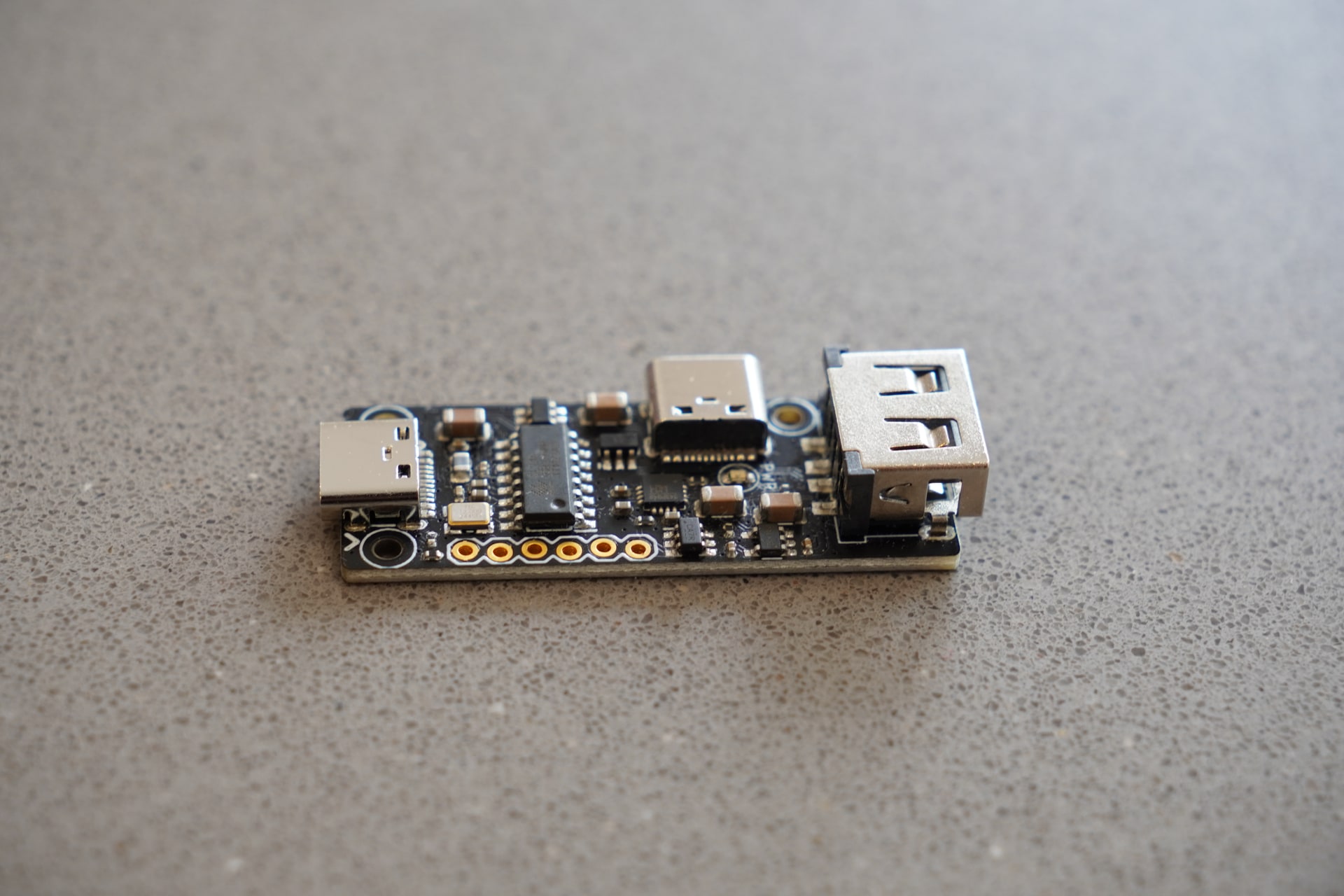
Connect pt1 to a computer over USB-C to add two USB sockets, a header-accessible USB port and a serial connection. The header also provides switched 5 V power, so a connected target can be powered, monitored and power-cycled from the same tool.
Pinout
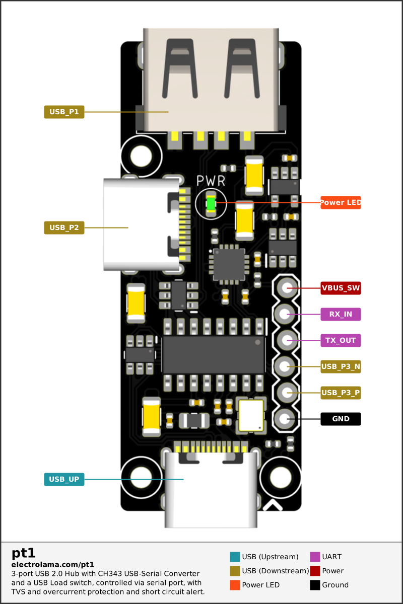
The diagram below identifies every connector, the six-pin expansion header, the switched-power output and the power indicator. Colours group the connections by function so the upstream USB port, downstream USB ports, UART, power and ground are easy to distinguish at a glance.
Features
- Four-port USB 2.0 hub, with one port used internally by the serial adapter
- USB-C upstream connection
- USB-C and USB-A downstream connections
- USB 2.0, UART and switched 5 V exposed on a 0.1-inch header
- Software-controlled USB power with current limiting and fault reporting
- TVS protection on the USB data lines
- LED indicator for switched USB power
- Three 2 mm mounting holes
Connections
The upstream USB-C port connects pt1 to the host. Its downstream ports are arranged as follows:
Host USB-C
    |
    `-- USB 2.0 hub
        |-- USB-C port
        |-- USB-A port
        |-- USB and UART header
        `-- Internal USB-to-UART adapter
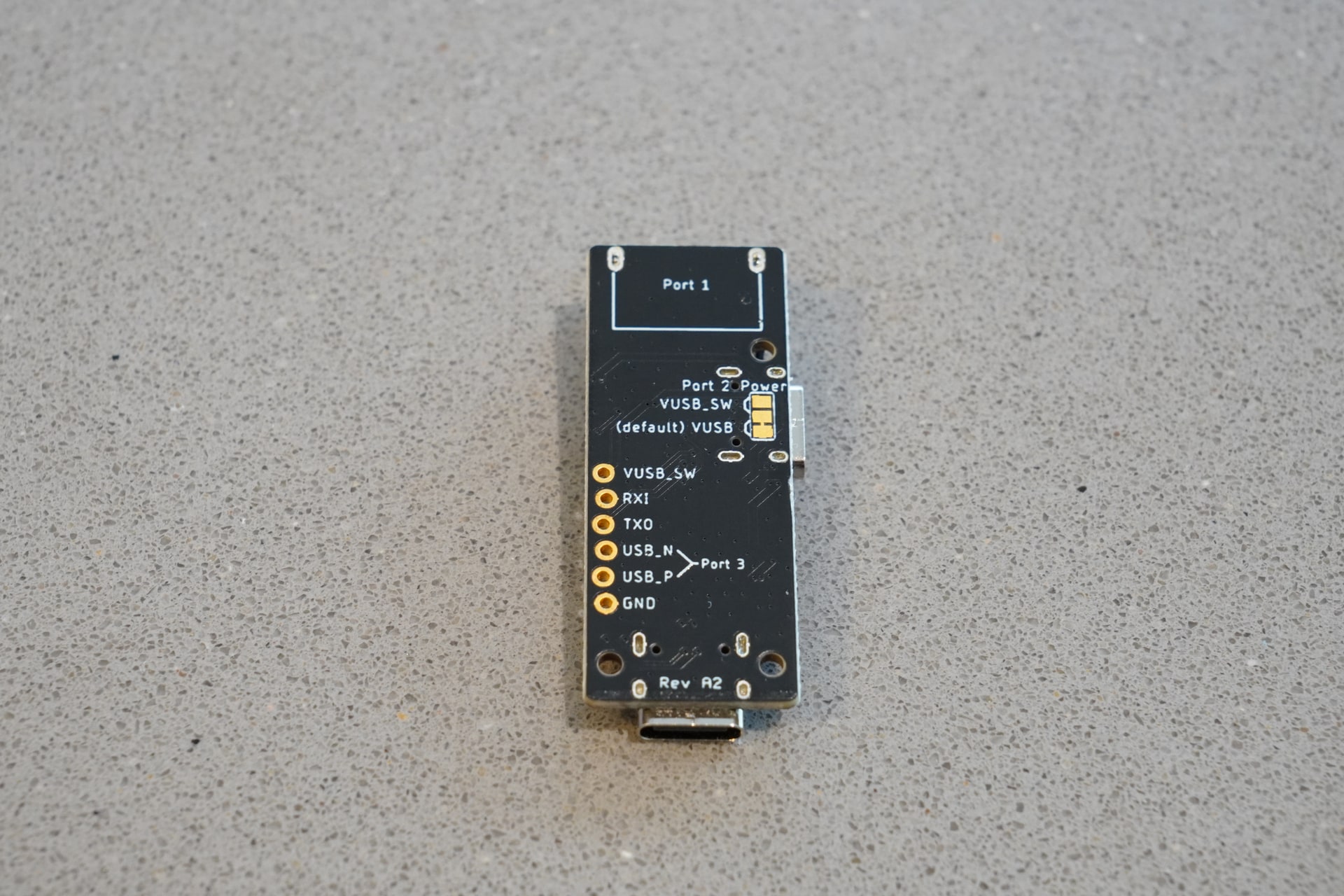
The six-pin header carries the third USB port, the UART and the switched power rail:
| Pin | Label | Function |
|---|---|---|
| 1 | VUSB_SW | Switched 5 V output |
| 2 | RXI | Serial receive; connect to the target's TX |
| 3 | TXO | Serial transmit; connect to the target's RX |
| 4 | USB_N | USB D− |
| 5 | USB_P | USB D+ |
| 6 | GND | Ground |
Power control and over-current detection
The USB-A port and header power pin are supplied through a protected load switch. The USB-C downstream port can be set to use either the switched rail or the unswitched USB supply using its solder jumper.
Vicuña has a dedicated pt1 mode that brings the board's power controls directly into the serial-terminal interface. It presents the DTR-controlled output as a clear power toggle and the RI fault signal as an integrated over-current indicator, so you can power-cycle a target, watch for faults and use its serial console from one place. This is the easiest way to use pt1's power-control features; the low-level details below are provided for custom integrations.
pt1 repurposes two familiar RS-232 modem-control signals from its USB-to-UART adapter, so power can be controlled and monitored through the serial port without a microcontroller or custom command protocol. These are logic-level control signals inside pt1; the board does not expose RS-232 voltage levels.
- DTR (Data Terminal Ready) controls power. The adapter's DTR output is active-low, so deasserting DTR makes the hardware output high and enables the load switch. In most serial libraries, including
pyserial, set DTR toFalsefor power on andTruefor power off. - RI (Ring Indicator) reports faults. The load switch pulls its active-low fault output low during an over-current or over-temperature condition. This is connected to the adapter's active-low RI input, so serial APIs normally report RI as asserted when a fault is present.
A short power-on delay keeps the switched output disabled while the board starts up. Some operating systems and terminal programs assert DTR automatically when opening a serial port, so control software should always set DTR explicitly.
The green PWR LED indicates that the switched 5 V rail is present. Although the load switch provides current limiting, the available current also depends on the host, power source and USB cable.
Python walkthrough
Install pyserial and replace COM12 with pt1's serial port. This example talks through each state change as it runs: opening the port switches power off, changing DTR switches it on and off, and reading RI checks for an over-current fault.
import time
import serial

PORT = "COM12"

print("Port is closed; the power switch retains its previous state")
time.sleep(4)

print(f"Opening {PORT} at 115200 baud...")
pt1 = serial.Serial()
pt1.port = PORT
pt1.baudrate = 115200
pt1.open()

try:
    print("Port open; DTR defaults to True, which switches power off")
    time.sleep(2)

    print("DTR = False -> power on")
    pt1.dtr = False
    time.sleep(2)

    print("DTR = True -> power off")
    pt1.dtr = True
    time.sleep(2)

    print("DTR = False -> power on; monitoring RI for faults")
    pt1.dtr = False

    while True:
        if pt1.ri:
            print("PROBLEM: over-current or over-temperature detected")
            pt1.dtr = True
            print("DTR = True -> power switched off")
            break

        print("Power OK; no fault detected")
        time.sleep(0.2)
finally:
    pt1.dtr = True
    pt1.close()
    print("Port closed; power left off")
The pauses are included to make the sequence easy to observe and can be shortened in your own control software. The example assumes the serial driver reports DTR and RI using the usual modem-signal polarity. Verify both signals on the target operating system before relying on them for unattended power or fault control.
Typical use
- Connect pt1 to the host through the upstream USB-C port.
- Wait for the USB hub and serial port to appear.
- Connect the target's UART to
TXO,RXIandGNDon the header. - Connect a USB device to either downstream socket or the header USB pair.
- Open the pt1 serial port in Vicuña and select its pt1 mode.
- Use the integrated power toggle to enable the switched output, and watch the over-current status while working with the target's serial console.
- Turn the target power off from the same control when finished.
3D-printed case
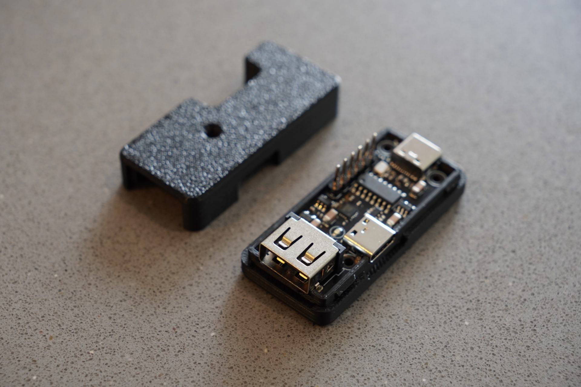
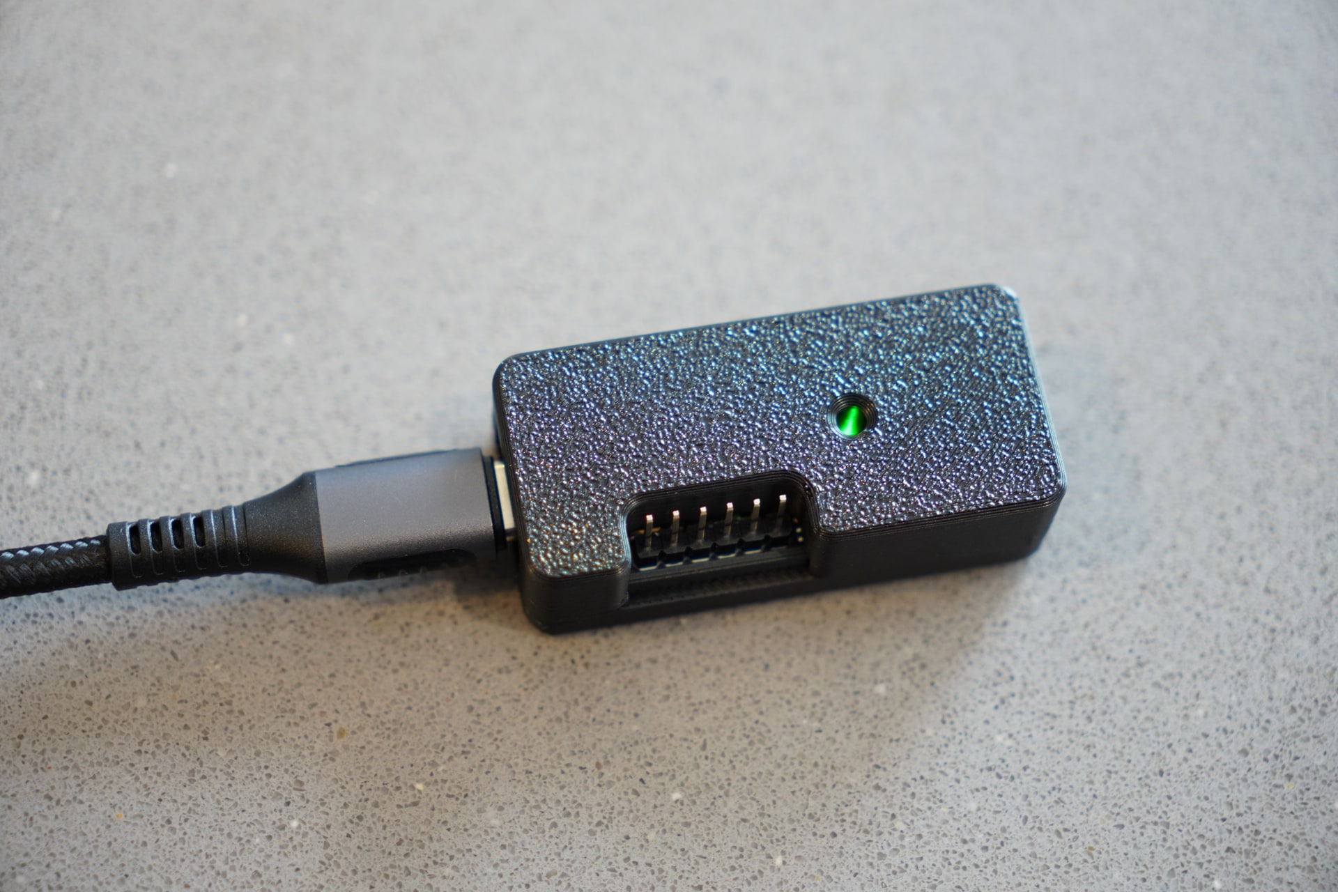
A two-piece 3D-printed case has also been designed for pt1. It neatly encloses the board while leaving the USB connectors, header and PWR LED accessible, giving the finished tool a tidy, compact appearance.
Design files
Design files and manufacturing packs are available in the pt1 GitHub repository.
Notes
- All ports carry USB 2.0 data only; the USB-C connectors do not provide SuperSpeed lanes.
- The UART remains available independently of the switched-power control.
- pt1 is a protected USB power switch and debug tool, not a calibrated USB power meter.
- Do not bridge both sides of the USB-C port's power-selection solder jumper at the same time.
Main components
- SL2.1A four-port USB 2.0 hub controller
- CH343P USB-to-UART bridge
- RT9742CGJ5 current-limited USB load switch
Acknowledgements
Thanks to: